Take the shear modulus of a metal, divide by about thirty, and you have the stress it should take to slide one plane of atoms over another. For an ordinary metal that is a number in the gigapascals.
Now measure it. A good annealed single crystal gives way at something like a thousandth of that.
That gap — three to four orders of magnitude, on the simplest possible experiment — was the largest unexplained number in metallurgy for most of the 1920s. You cannot round it away or blame the apparatus. Something was badly wrong with the picture of a crystal as a perfect stack of atoms.
In this post:
- Why a perfect crystal would be far stronger than any real metal
- What a dislocation actually is, in two pure flavours
- Why one line defect makes an entire metal soft
- Why every strengthening method ever invented is the same idea
- The paradox: both more dislocations and none at all make metal stronger
Why a perfect crystal should be far stronger than it is
Picture shearing a crystal the obvious way: grip the top half, grip the bottom half, and slide one over the other as a block. Every bond across the slip plane has to stretch, break and reform at the same instant.
Yakov Frenkel did this calculation in 1926 with a sinusoidal bond-force law and got a maximum shear stress of roughly G/2π, where G is the shear modulus. Better models bring it down to about G/30 [1]. Either way you land in the gigapascals, and either way real metals miss it by a factor of thousands.
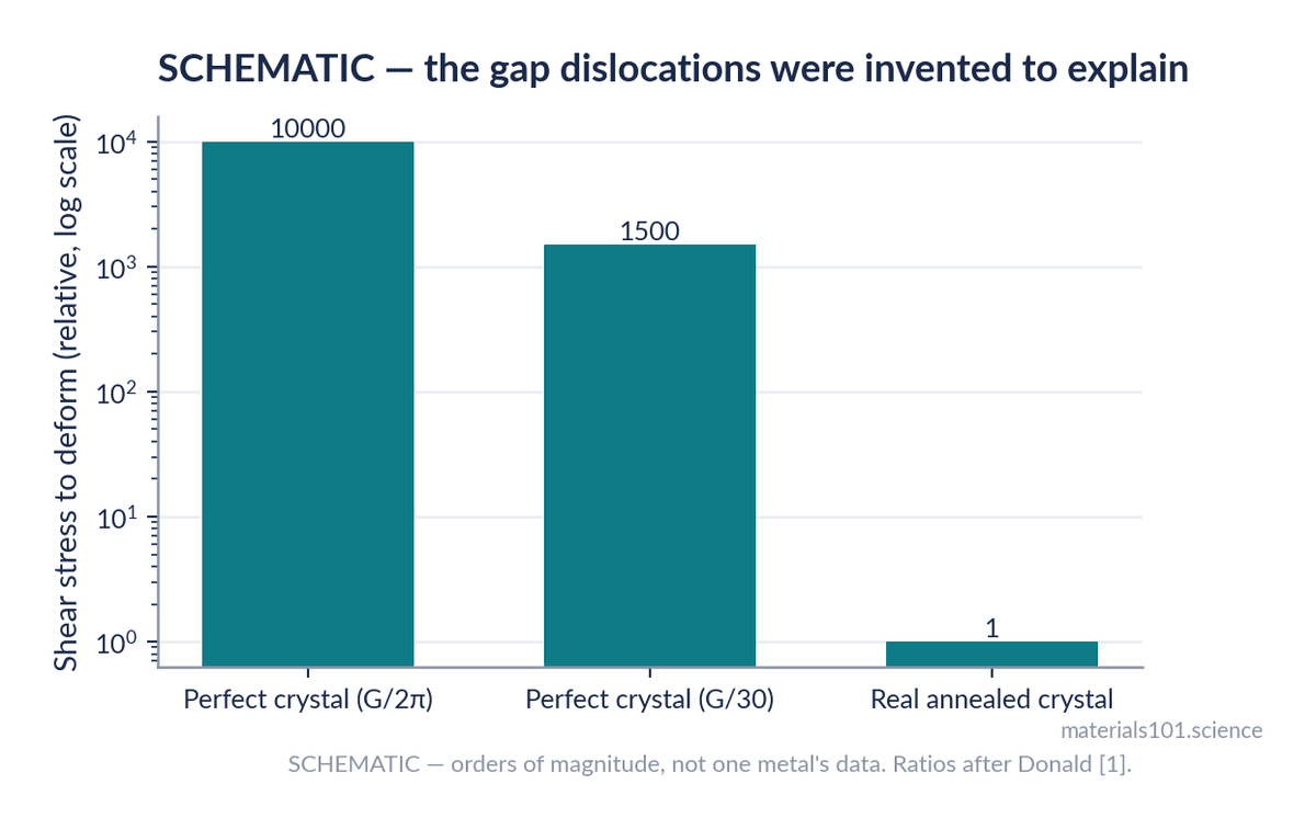
A wrong answer by 10% is a bad model. A wrong answer by 1000× means you are describing a different object from the one on the bench.
What a dislocation is
The resolution, proposed independently by Orowan, Polanyi and Taylor in 1934, was that real crystals are not perfect. They contain line defects, and those lines let the crystal shear a few atoms at a time rather than all at once.
The simplest kind is an edge dislocation: an extra half-plane of atoms that stops partway through the crystal. The row above the slip plane has one more atom in it than the row below.
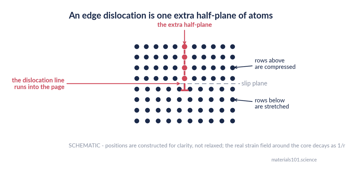
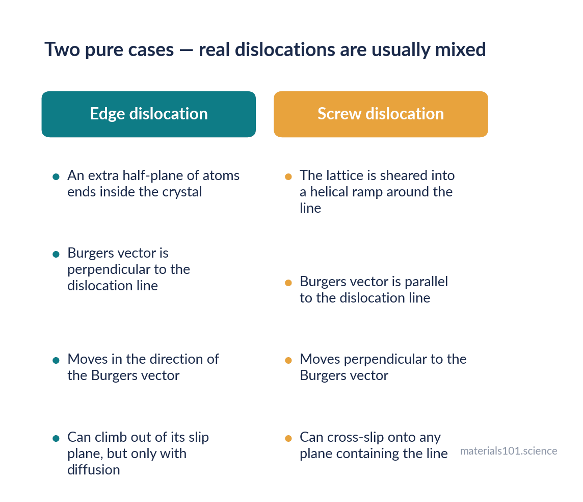
Two things define it. The dislocation line is the edge of the extra plane — in the figure it runs straight into the page. The Burgers vector is the lattice step you come up short by if you trace a closed loop around the line, atom by atom, that would have closed in a perfect crystal. It measures how much slip the dislocation carries, and for a full dislocation it is one lattice translation.
The other pure case is a screw dislocation, where the lattice is sheared into a continuous helical ramp around the line, so a circuit around it advances you one step along the axis, like a spiral car park.
Why one line makes a whole metal soft
Here is the mechanism, and the standard analogy is the right one because the physics really is the same.
Shift a heavy rug across a floor by dragging the whole thing and you fight the friction of its entire area at once. Put a ruck in one end and walk the ruck across instead, and you only ever fight the friction under the ruck. The rug ends up displaced by the same amount. The force you needed was a small fraction.
A dislocation is the ruck. At any instant only the bonds in the immediate core are being broken and remade — a handful of atoms, not the whole plane. The stress needed to keep the line moving through an otherwise perfect lattice is the Peierls–Nabarro stress, and it is small compared with the Frenkel estimate because it is a local cost, not a global one.
Going deeper
Dislocation glide carries plastic strain at a rate set by the Orowan relation, γ̇ = ρ b v, where ρ is the mobile dislocation density, b the magnitude of the Burgers vector, and v the average glide velocity. The practical consequence is that there are two independent ways to accommodate a high strain rate: move the dislocations you have faster, or produce more of them. Metals do both, and because v cannot exceed the shear wave speed, the second route is what dominates at high rates — which is why strain-rate sensitivity and dislocation multiplication are the same subject.
Why every strengthening method is one idea
Once you accept that metals deform by dislocation motion, strengthening stops being a list to memorise. Anything that makes a dislocation’s journey harder makes the metal stronger. That is the whole subject.
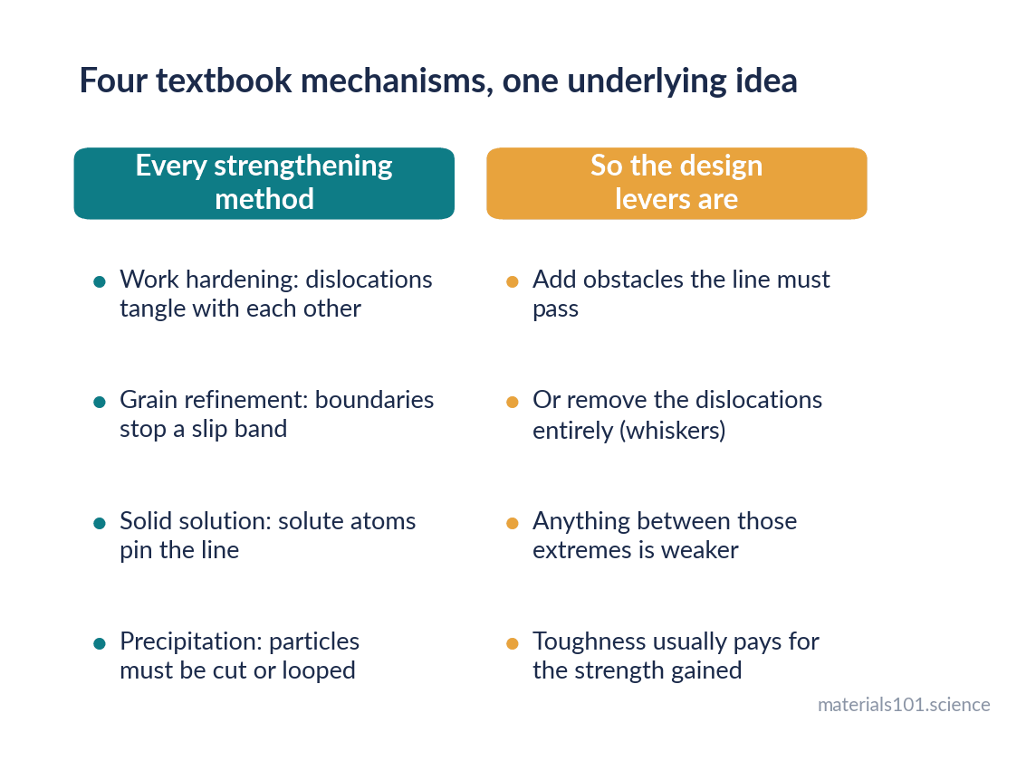
- Work hardening. Deform a metal and its dislocation density rises by orders of magnitude. The lines tangle, intersect and trap one another, so each new one has a harder time moving. This is why a paperclip gets stiffer and then snaps where you keep bending it, and why cold-worked metal needs annealing before it can be worked further.
- Grain refinement. A grain boundary is a change in lattice orientation, so a slip plane does not continue across it. Dislocations pile up against the boundary instead, and the pile-up back-stress opposes the ones behind. Smaller grains mean more boundaries and shorter pile-ups.
- Solid solution strengthening. A solute atom of the wrong size strains the lattice around it. That strain field interacts with the dislocation’s own, and the line has to be pushed past.
- Precipitation hardening. Second-phase particles force a choice: the line cuts through the particle, or it bows around and leaves a loop behind. Either costs stress, and the peak strength sits where the two mechanisms cross over.
In practice
This is why the same alloy arrives with wildly different properties depending on temper, and why a materials certificate that quotes composition alone tells you much less than it appears to. Composition sets what obstacles are available; thermal and mechanical history sets how many there are and how they are arranged. Two bars of nominally identical 6061 aluminium, one in the O temper and one in T6, differ in yield strength by several times — and nothing in the chemistry distinguishes them.
The paradox worth remembering
If dislocations make metals weak, a crystal with none should be strong — and it is. Flawless metal whiskers grown a few micrometres across approach the theoretical strength, because there is no dislocation to move and the crystal has to shear the hard way.
But a crystal stuffed with dislocations is also strong, because they obstruct each other.
So strength as a function of dislocation density is not a straight line. It falls steeply from the theoretical value as the first dislocations appear, bottoms out in the annealed state, and climbs again as cold work piles them in. Annealed metal sits near the bottom of that curve — the softest condition available, which is exactly why annealing is what you do when you need to form something.
Common misconceptions
“A dislocation is a missing atom.” No — that is a vacancy, a point defect. A dislocation is a line: it extends through the crystal and terminates only at a surface, a grain boundary, or on itself in a loop. It cannot simply stop in the middle of a perfect region.
“Dislocations are damage.” They are a normal feature of essentially every metal crystal, present before any load is applied, and they are what makes metals formable. A metal with no way to move dislocations is not a better metal; it is a ceramic.
“More dislocations always means weaker.” The opposite, past the annealed minimum. Work hardening is dislocation density doing the strengthening.
Key takeaways
- A perfect crystal should shear at roughly G/30; real metals give way at about a thousandth of that, and dislocations are the explanation [1].
- A dislocation lets a crystal slip a few atoms at a time instead of a whole plane at once — the rug-ruck mechanism.
- Edge and screw are the two pure characters; real dislocations are mixed, and only screw segments can cross-slip.
- Every strengthening mechanism is an obstacle to dislocation motion.
- Strength versus dislocation density is U-shaped: both a flawless whisker and a heavily cold-worked bar are strong, and the annealed state in between is the soft one.
Frequently asked questions
What is a dislocation in simple terms?
A line defect in a crystal where the regular stacking of atoms is interrupted — most simply, an extra half-plane of atoms that ends partway through. It lets the crystal deform by shifting a few atoms at a time rather than sliding whole planes.
What is the difference between an edge and a screw dislocation?
The Burgers vector is perpendicular to the line for an edge dislocation and parallel to it for a screw. The practical difference is that a screw dislocation can cross-slip onto another plane to bypass an obstacle, while an edge dislocation can only leave its slip plane by climb, which needs diffusion and therefore heat.
Why do dislocations make metals weaker?
Because they let slip happen sequentially. Only the bonds at the moving core break at any instant, so the stress needed is far below the stress required to shear an entire plane simultaneously.
What is the Burgers vector?
The closure failure of an atom-by-atom circuit drawn around a dislocation line — the lattice step you come up short by. It gives both the magnitude and direction of the slip the dislocation carries.
Can you see dislocations?
Yes. Transmission electron microscopy images them routinely through the strain contrast around the line, and etch pitting reveals where they intersect a polished surface.
Next read
- BCC vs FCC vs HCP: why crystal structure decides ductility
- What is a unit cell? Crystallography from scratch
- Annealing vs normalizing vs tempering
Spotted an error? Tell me — corrections are made in public.
References
- A. M. Donald, Crystalline Solids 1, lecture notes, University of Cambridge. Frenkel estimate of theoretical shear strength and the measured discrepancy. https://people.bss.phy.cam.ac.uk/~amd3/teaching/A_Donald/Crystalline_Solids_1.pdf