
Body-centred cubic steel has 48 slip systems. Face-centred cubic copper has 12.
The one with 48 is the one that shatters in the cold.
That is not a trick of counting. It is the clearest example in materials science of a rule worth internalising early: what a crystal can do is decided by the quality of its slip planes, not their number. And the quality comes from one thing — how tightly the atoms in those planes are packed.
By the end of this post you will be able to explain the difference between BCC, FCC and HCP metals in terms of what actually matters in service: how many ways the crystal can shear, how good those ways are, and what happens to them when the temperature drops.
In this post:
- What “close-packed” means, and why it decides everything downstream
- Why FCC and HCP differ by exactly one layer
- The three structures side by side, with the numbers
- Why a transition temperature exists at all
- How to use this when you choose a material
What does close-packed actually mean?
A close-packed plane is a layer of atoms arranged as tightly as spheres can be in two dimensions — each atom touching six neighbours, like oranges on a market stall. Stack those layers and you get the two close-packed structures, FCC and HCP. BCC packs less efficiently, and it pays for that in a way that shows up as a shattered component on a cold morning.
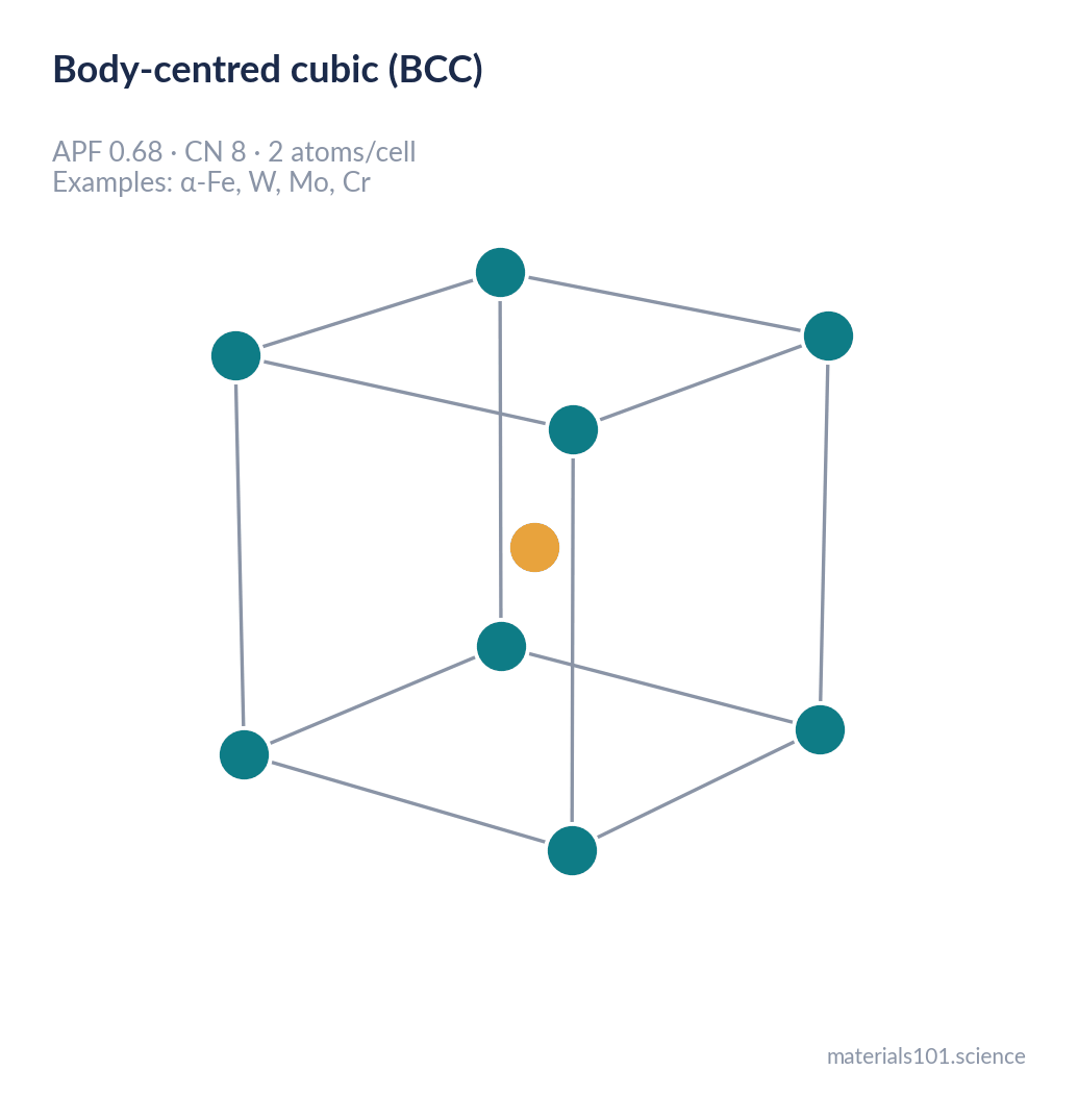
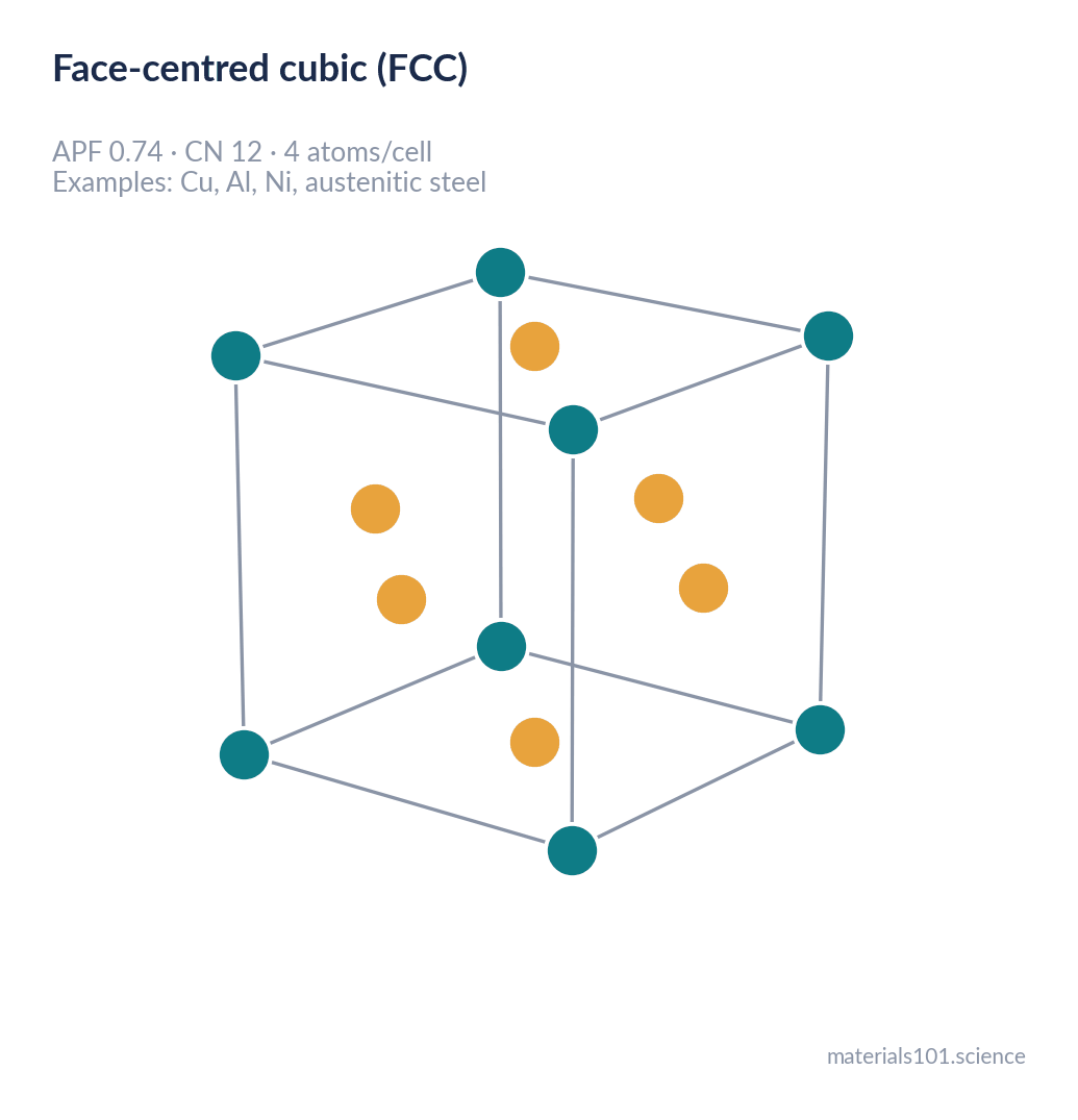
Two numbers describe the packing. The atomic packing factor (APF) is the fraction of space filled: 0.74 for FCC and HCP, 0.68 for BCC. The coordination number (CN) is how many nearest neighbours each atom has: 12 for FCC and HCP, 8 for BCC [3].
Those sound like modest differences. They are not, because metals do not deform by pulling bonds apart. They deform by sliding one plane of atoms over another. Planes slide most easily when they are smooth — when the atoms in them are packed as tightly as possible, so the bumps a sliding plane must climb are as shallow as geometry allows.
FCC and HCP differ by exactly one layer
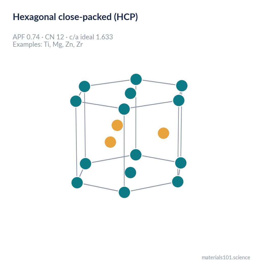
Here is the part that rarely gets said plainly in a first course. FCC and HCP have the same packing efficiency, the same coordination number, and the same close-packed layers. They differ only in where the third layer goes.
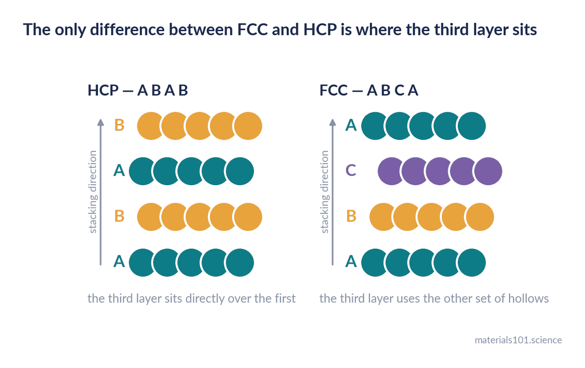
Lay down a close-packed layer, call it A. The next layer sits in the hollows, call it B. Now the third layer has two choices: return to positions directly above A, or occupy the other set of hollows, which we call C.
- Choose A, and you get ABABAB — hexagonal close-packed.
- Choose C, and you get ABCABCABC — face-centred cubic.
One decision, repeated. From it follows the fact that FCC has four equivalent sets of close-packed planes while HCP has only one — and that difference is why titanium is difficult to form and copper is not.
The three structures, side by side
| FCC | BCC | HCP | |
|---|---|---|---|
| Atomic packing factor | 0.74 | 0.68 | 0.74 |
| Coordination number | 12 | 8 | 12 |
| Atoms per unit cell | 4 | 2 | 6 |
| Close-packed planes | {111}, four sets | none | basal (0001), one |
| Slip systems | 12, all close-packed | 48, none close-packed | 3 easy (basal) |
| Behaviour when cold | unchanged | ductile-to-brittle transition | twins, strongly anisotropic |
| Examples | Cu, Al, Ni, Ag, 304/316 stainless | α-Fe, W, Mo, Cr, ferritic steel | Ti, Mg, Zn, Zr, Co |
The row that matters is the second from the bottom, and it needs the row above it to make sense.
Slip systems: the count is not the point
A slip system is a plane the crystal can shear along, paired with a direction it can shear in. The count alone tells you very little; whether the plane is close-packed tells you almost everything.
FCC has four {111} planes, each with three ⟨110⟩ directions — twelve systems, every one close-packed in both plane and direction [4]. Load an FCC crystal any way you like and several favourably oriented, low-resistance slip systems are available.
BCC looks better on paper. Counting {110}, {112} and {123} planes gives 48 systems. But no plane in a BCC crystal is close-packed; the best of them, {110}, is still noticeably bumpier than an FCC {111} plane. BCC slip is therefore not impossible — it is expensive, and the price depends sharply on temperature.
HCP has the opposite problem. Its basal plane is genuinely close-packed, but there is only one of it, giving three easy slip systems. Load it perpendicular to that plane and easy slip is simply unavailable.
Going deeper The governing quantity is the Peierls–Nabarro stress: the intrinsic lattice resistance a dislocation must overcome to move one atomic spacing. It scales roughly as exp(−2πw/b), where w is the dislocation core width and b the Burgers vector. Wide, spread-out dislocations on smooth close-packed planes (FCC) have a low Peierls stress with almost no temperature dependence. Narrow, compact screw dislocations on non-close-packed planes (BCC) have a high Peierls stress that depends strongly on thermal activation. That single difference is the root of everything in the next section [4].
Why a transition temperature exists at all
Two curves explain it, and most textbooks draw only one of them.
The first is the yield stress — the stress needed to move dislocations. In BCC metals it climbs steeply as temperature falls, because dislocation motion needs thermal energy it is no longer getting. In FCC metals it barely moves.
The second is the cleavage fracture stress — the stress needed to split the crystal along a plane. It is nearly independent of temperature in both.
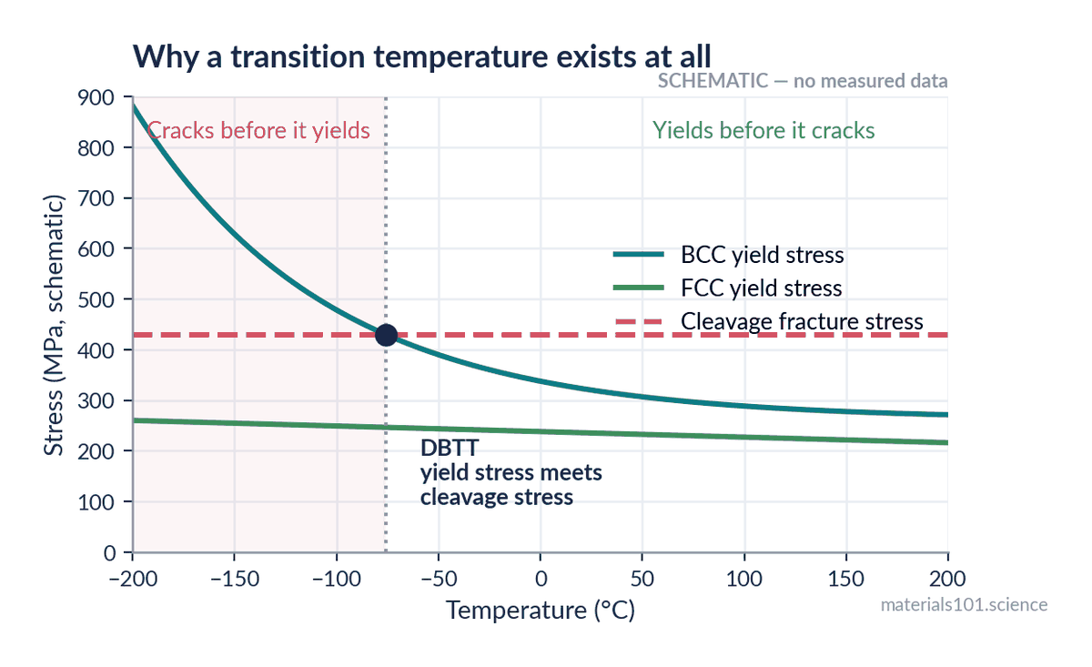
Whichever mechanism requires less stress is the one that occurs. Above the crossing point, a BCC metal yields before it cracks and behaves ductilely. Below it, cracking is the cheaper option and the metal fails by cleavage — fast, flat, and absorbing almost no energy. That crossing point is the ductile-to-brittle transition temperature (DBTT).
FCC metals have no crossing point. Their yield stress never climbs to meet the cleavage stress, which is why austenitic stainless steels are the standard choice for cryogenic tanks. Tensile and fracture testing of 304L at 300 K, 77 K and 20 K finds ductile fracture at all three temperatures, with no transition — even at liquid-hydrogen temperature [2].
What you measure, rather than what you draw, looks like this. The points below are Charpy V-notch results for API 5L X52 line pipe steel — an unremarkable ferritic pipeline grade — as reported by NIST [1].
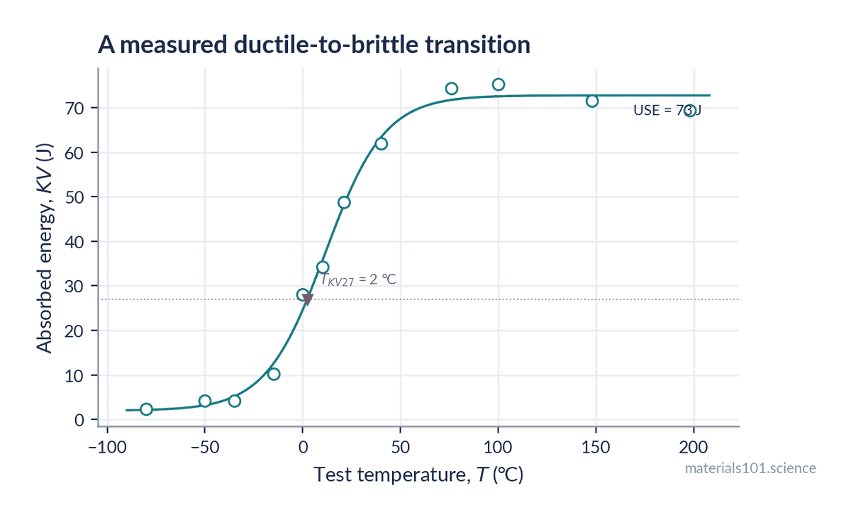
Read the numbers rather than the shape. At −80 °C this steel absorbs 2.4 J. At +76 °C it absorbs 74.3 J — a factor of 31, on the same steel, with no change in composition or strength. The fitted curve puts the mid-transition temperature at 11.5 °C, which agrees with the 11.7 °C that NIST reports from the same data by a different method [1], and the common 27 J specification index is reached at +2 °C.
Sit with that last figure for a moment. A pipeline grade whose 27 J point is only two degrees below the freezing point of water is fine in Chennai and marginal in a Delhi January. Nothing about the steel changed; the service temperature did.
The transition is not a fixed material constant, and treating it as one is how people get hurt. It shifts with composition — more carbon raises it, manganese lowers it. It shifts with grain size: grain refinement is the only common strengthening mechanism that raises strength and lowers the transition temperature at the same time. It shifts with section thickness, because thick sections constrain the material into plane strain. And it shifts with loading rate, which is why a plate can pass a slow tensile test and still shatter under impact.
It is also not a steel-only problem. Tungsten, the highest-melting metal there is, has a transition temperature reported well above room temperature and strongly dependent on its recrystallisation state [7]. Tungsten components are brittle in your hand and must be worked hot.
In practice This is why Charpy V-notch testing (ASTM E23) exists, and why pressure-vessel, line-pipe and structural specifications quote impact energy at a stated temperature — “27 J at −20 °C” — rather than tensile strength alone. If a component will see −20 °C, “the steel is strong enough” is not an answer. The question is whether it is still tough at the lowest temperature it will ever see, at the highest loading rate it will ever see, in the thickest section you intend to use. For genuinely cold service the usual answers are austenitic stainless or aluminium alloys, because they are FCC, or 9% nickel steel, because nickel pushes the transition far below service temperature.
Why HCP metals are the awkward ones
Titanium and magnesium do not fit the tidy story. With only three easy slip systems, an HCP crystal cannot generally accommodate an arbitrary shape change — the von Mises criterion requires five independent slip systems for that. HCP metals do two things instead.
First, they twin: a region of the crystal reorients in a coordinated shear, producing deformation the available slip systems could not. Second, they behave anisotropically — rolled magnesium sheet is markedly stronger in one direction than another, and rolled titanium develops a strong texture engineers must design around rather than ignore.
This is why magnesium sheet is difficult to form at room temperature and much better behaved warm, typically in the region of 200–250 °C, where additional non-basal slip systems become active and formability improves markedly [8]. It is also why workhorse titanium alloys such as Ti-6Al-4V are two-phase: the BCC β phase supplies slip systems the HCP α phase lacks.
How to use this when you choose a material
| If you need | Look at | Because |
|---|---|---|
| Toughness at cryogenic temperature | FCC: austenitic stainless, aluminium, Cu alloys | no transition temperature to fall below |
| Maximum strength, moderate temperature | BCC: quenched and tempered steels | high lattice resistance is strength |
| Deep-formed sheet | FCC: aluminium, brass, austenitic stainless | twelve close-packed systems, isotropic |
| Lightweight structure, warm forming | HCP: Mg and Ti alloys, formed hot | few easy systems cold, many more above ~200 °C |
| High-temperature service | FCC-based: Ni superalloys | ductility retained; creep becomes the limit instead |
| Anything thick, cold and impact-loaded | test it, do not select from a table | thickness and rate shift the transition |
The last row is the one worth remembering. Crystal structure tells you which failure modes are available to a material. Processing, composition and geometry decide whether they actually happen.
Common misconceptions
- “FCC metals are stronger than BCC metals.” Usually the reverse. BCC ferritic and martensitic steels reach higher strengths; FCC metals are more ductile and far tougher when cold. Strength and toughness are different properties and they often trade against each other.
- “More slip systems means more ductility.” BCC has 48 and still goes brittle. Whether the systems are close-packed, and how much thermal help they need, is what counts.
- “Higher packing factor means a denser metal.” APF is a geometric fraction, not a density. Aluminium is FCC with APF 0.74 and tungsten is BCC with APF 0.68, yet tungsten is about seven times denser — that comes from atomic mass and atomic radius, not from stacking.
- “A metal’s crystal structure is fixed.” Iron is BCC below 912 °C, FCC between 912 °C and 1394 °C, and BCC again above that. Every steel heat treatment exists because of those transitions.
Key takeaways
- FCC and HCP both pack at 74% and differ only in where the third close-packed layer sits; BCC packs at 68% and has no close-packed plane at all.
- FCC’s twelve close-packed slip systems make its yield stress nearly temperature-independent, so FCC metals stay ductile to cryogenic temperatures.
- A ductile-to-brittle transition appears wherever a rising yield stress crosses a flat cleavage stress — a BCC problem, and a design constraint rather than a defect.
- The transition temperature moves with composition, grain size, section thickness and loading rate, so it must be tested rather than looked up.
- HCP metals have only three easy slip systems, so they twin, deform anisotropically, and are usually formed warm.
Frequently asked questions
What is the main difference between BCC, FCC and HCP?
FCC and HCP are close-packed structures filling 74% of space with 12 nearest neighbours; BCC fills 68% with 8. In practice the difference is slip: FCC has twelve close-packed slip systems and stays ductile when cold, BCC has none that are close-packed and becomes brittle below its transition temperature, and HCP has only three easy systems so it deforms partly by twinning.
Why are FCC metals more ductile than BCC metals?
Because FCC slip planes are close-packed, the lattice resistance to dislocation motion is low and almost independent of temperature. BCC dislocations need thermal energy to move, so cooling raises the yield stress until cleavage fracture becomes the easier option.
What is the difference between FCC and HCP if both are close-packed?
Only the stacking sequence. HCP repeats ABAB, putting the third layer back above the first; FCC repeats ABCABC, putting it in the other set of hollows. This gives FCC four equivalent sets of close-packed planes and HCP only one, which is why FCC metals are far more formable.
Which crystal structure is strongest?
No structure is strongest by itself. BCC metals such as tungsten and martensitic steel reach the highest strengths, but strength comes from composition, grain size and defect structure — the lattice only sets what is possible.
Why does iron change from BCC to FCC when heated?
Above 912 °C the FCC arrangement has lower free energy, largely because of its higher vibrational entropy, so austenite becomes stable. Cooling reverses it, and the cooling rate decides whether you get ferrite, pearlite, bainite or martensite.
Is stainless steel BCC or FCC?
It depends on the grade. Austenitic grades such as 304 and 316 are FCC and are the ones used for cryogenic service; ferritic grades such as 430 are BCC; martensitic grades such as 410 are body-centred tetragonal, a distorted BCC.
Next read
- The Liberty ships that broke in half — what happens when a transition temperature is left out of the specification
- What is a unit cell? Crystallography from scratch — the wider map this post sits inside
Data sources and references
Every number plotted in this post comes from a published source. The two
schematic figures say so on their face and carry no data.
- E. Lucon, C. N. McCowan and R. L. Santoyo, Impact Characterization of Line Pipe Steels by Means of Standard, Sub-Size and Miniaturized Charpy Specimens, NIST Technical Note 1865, National Institute of Standards and Technology, 2015. doi:10.6028/NIST.TN.1865 — source of the X52 Charpy data, the upper-shelf energy and the reported transition temperature.
- M.-S. Kim, T. Lee, J.-W. Park and Y. Kim, Tensile and Fracture Characteristics of 304L Stainless Steel at Cryogenic Temperatures for Liquid Hydrogen Service, Metals 13(10), 1774, 2023. doi:10.3390/met13101774 — 304L behaviour at 300, 77 and 20 K.
- W. D. Callister and D. G. Rethwisch, Materials Science and Engineering: An Introduction, 10th ed., Wiley, 2018 — packing factors, coordination numbers, allotropy of iron.
- D. Hull and D. J. Bacon, Introduction to Dislocations, 5th ed., Butterworth-Heinemann, 2011 — slip systems, the Peierls–Nabarro stress, BCC screw dislocation behaviour.
- ASTM International, ASTM E23: Standard Test Methods for Notched Bar Impact Testing of Metallic Materials — the test behind every Charpy value quoted here.
- J. F. Knott, Fundamentals of Fracture Mechanics, Butterworths, 1973 — the yield-stress / cleavage-stress construction shown schematically above.
- Brittle-ductile transition temperature of recrystallized tungsten following exposure to fusion relevant cyclic high heat load, Journal of Nuclear Materials, 2020 — supports the statement about tungsten only; author list to be completed.
- Improvement of formability from room temperature to warm temperature in AZ-31 magnesium alloy, Journal of Materials Processing Technology — supports the magnesium warm-forming statement only; author list to be completed.
Publication-grade versions of the data figure (600 dpi PNG and vector PDF, journal
column width, ticks inward, fitted parameters reported) are generated alongside the
blog figures and are free to reuse with attribution to the original data source.
Written by Dinesh Varma, PhD scholar in computational materials science.
Spotted an error? Tell me — corrections are credited.